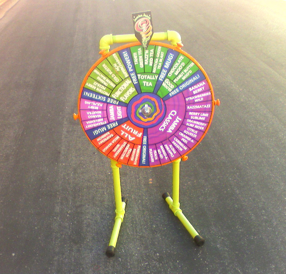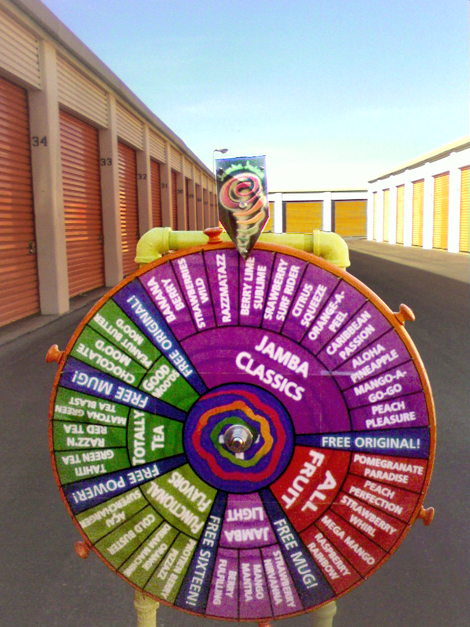

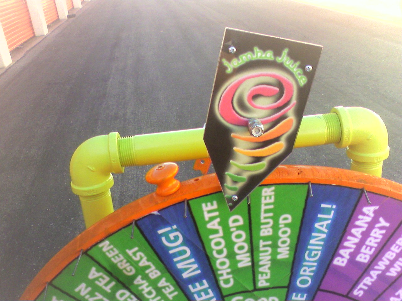
I designed the center of the wheel to look like a blender whipping up a smoothie, you can see the metal blades in the center. I sorted the smoothies in the same order they were on the Jamba menu, and padded the areas with bonus prize slots.
The actual wheel was a pre-made wooden circle available at most hardware stores. I bought the biggest size available. The knobs around the edge are also prefabs I simply screwed into pilot holes I had drilled beforehand. I gave the whole thing a nice orange coat. I had the graphics printed out at a Kinko's and attached them to the wheel with spray-glue. Around the edge I hammered in nails where the black lines radiated outward. The wheel was complete!
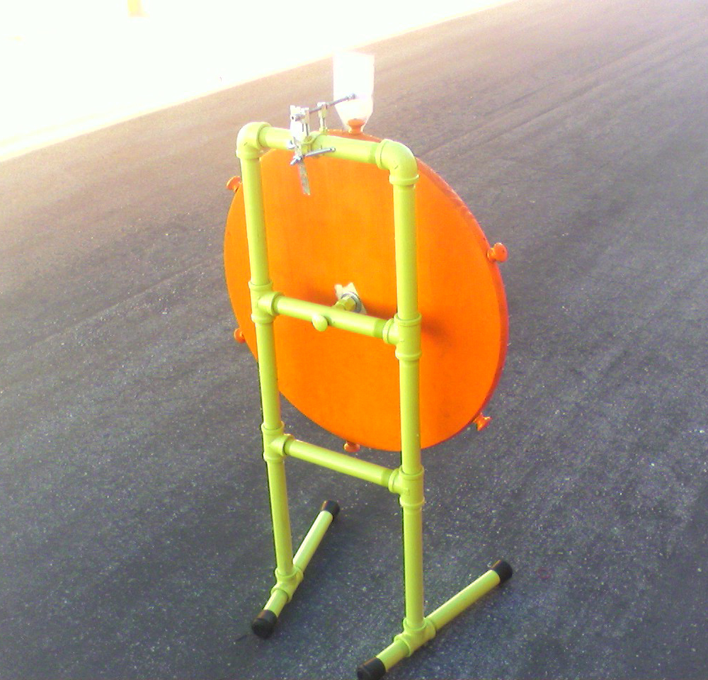
To build the frame I just bought some pre-threaded galvanized pipe from home depot, plus some tee-joints and right-angle pipe fittings. I stuck some generic rubber feet on the bottom and covered everything with a sexy chartreuse green. One interesting challenge that I completely overlooked was the assembly of the pipes. As you can see below, two of the sections have pipes making a complete square... The problem is connecting the last two bits. Once everything is attached, how do you rotate/twist the last fitting to screw it on the pipe?
My solution was to screw the horizontal beams in super-tight on the right, then attach the left sides and unscrew the horizontal beams slightly, while simultaneously screwing them into the other side.... if that makes sense. To reiterate I had to unscrew the horizontal pipes from one side while screwing them into the other to keep a nice balance.
To build the flipper, I printed out a template and headed over to my local Tap Plastics. I had two identical pieces of Plexiglas cut for a few bucks. I used this and a couple bolts to sandwich the Jamba logo graphic I had printed out.
Below is the public facing side of the flipper all done:
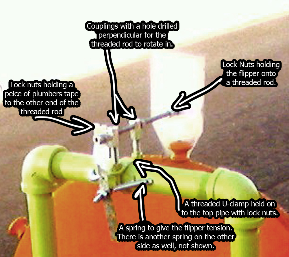
For the flipper mechanism I used a bunch of off-the-shelf hardware parts and a little creativity. I've labeled everything below, but here's a run down of the process:
- I got a U-Bolt style clamp and a couple lock nuts. I clamped the u-bolt upside-down to the top green pipe, leaving it's exposed threads pointing upwards.
- I drilled two holes perpendicularly in some threaded couplings, and screwed them half-way on the u-bolt legs.
- I inserted a threaded-rod through the drilled out couplings. Now I had a threaded rod that could rotate and was mounted above the wheel.
- I used lock nuts to attach / clamp down the flipper.
- I used lock nuts to attach / clamp down a piece of plumbers tape to the back of the threaded rod - this created a lever-arm.
- I attached a couple springs to the lever-arm to give the flipper some tension, and mounted the the springs to the top-green pipe.
Over all, the project came out so-so. It looked great, but had some problems. First let's take a look at the finished thing. Below is a shot right after it was finished, and a video of it in action. Warning, I filmed it on an ancient camera phone circa 2006/2007, so the quality is pretty bad.